CS184/284A Spring 2025 Homework 2 Write-Up
Link to webpage: Our website!
Link to GitHub repository: github.com/orgs/cal-cs184-student/teams/waffle2
Overview
In this homework, we implemented key concepts in geometric modeling. In particular, we focused on Bezier curves and surfaces, and triangle meshes with half-edges. We implemented de Casteljau's algorithm for Bezier curves and extended the algorithm to Bezier surfaces. We also implemented area-weighted vertex normals for smoother shading, programmed edge flips and edge split operations, as well as implemented loop subdivision for mesh upsampling. I found it interesting how easily I was able to extend de Casteljau's algorithm from Bezier curves to surfaces. Furthermore, figuring out edge flips and edge splits was the most fun part! Debugging got confusing, but worth the time.Section I: Bezier Curves and Surfaces
Part 1: Bezier curves with 1D de Casteljau subdivision
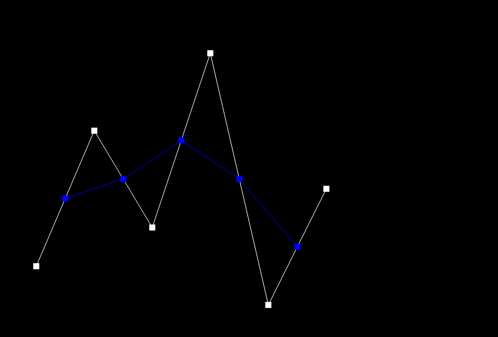
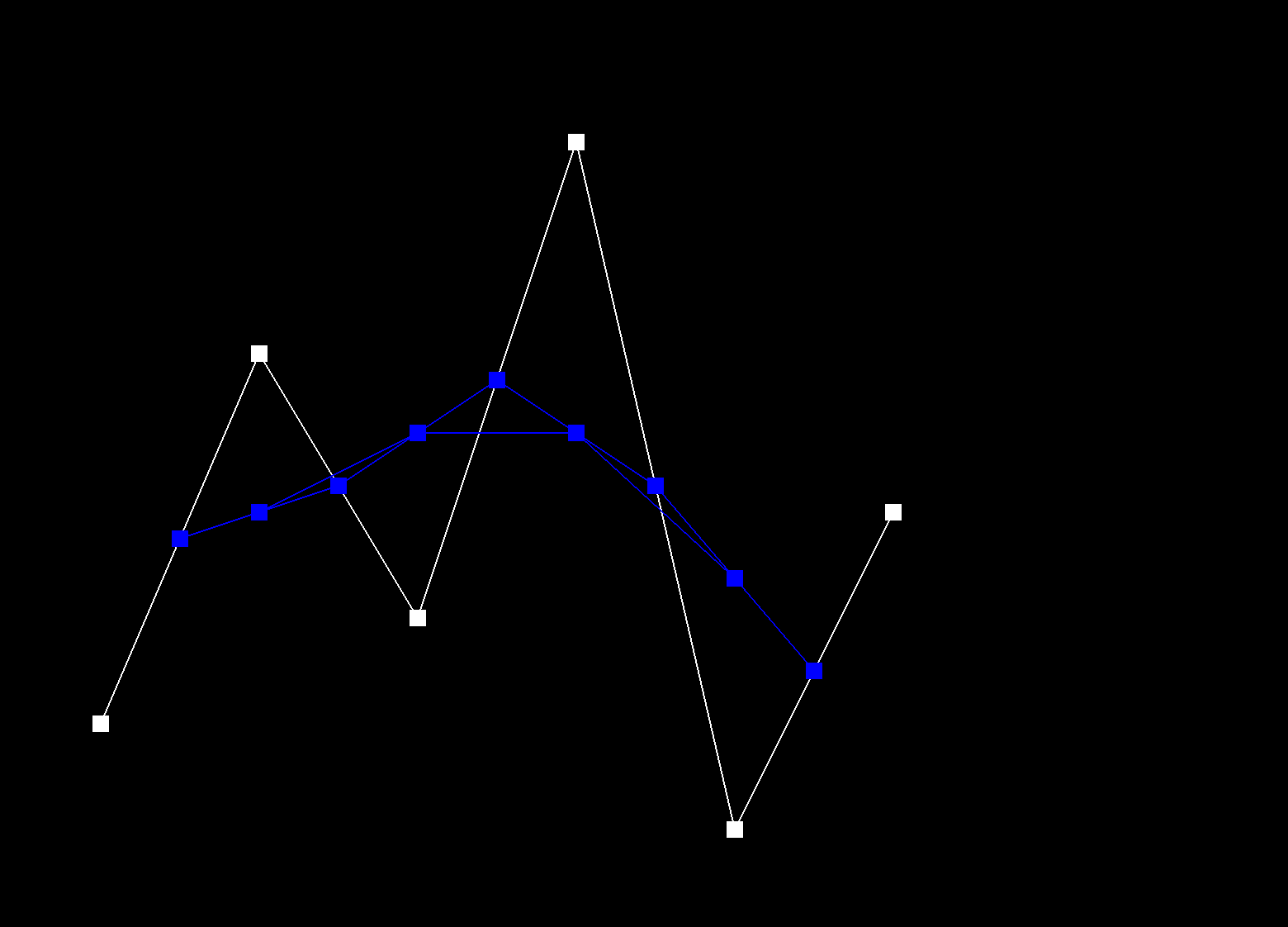
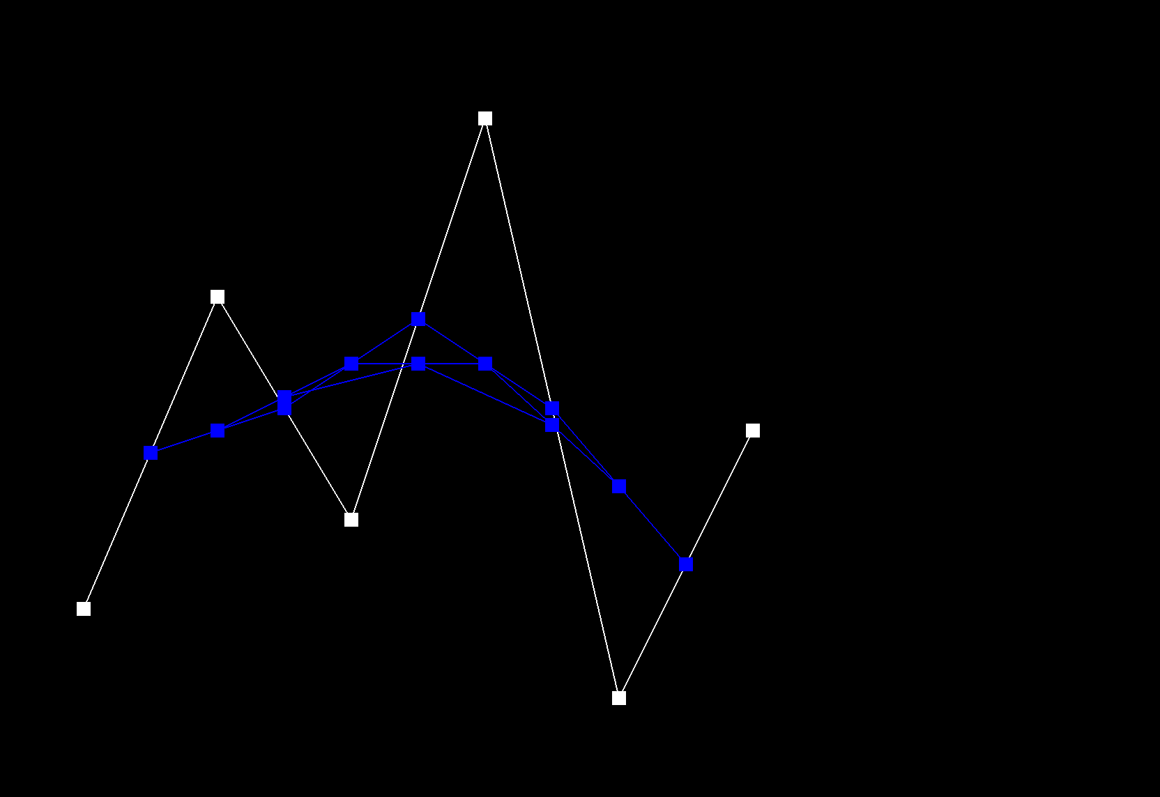
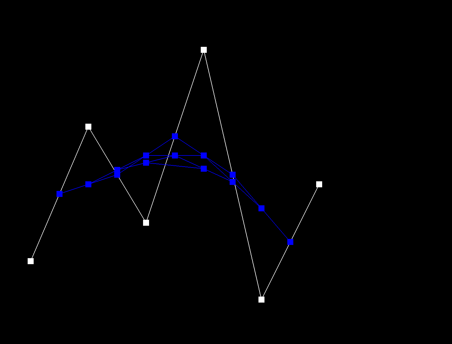
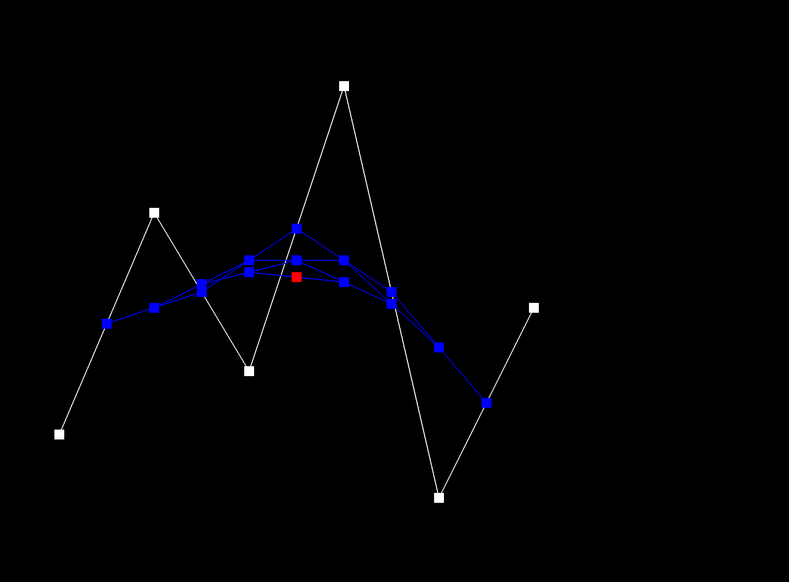
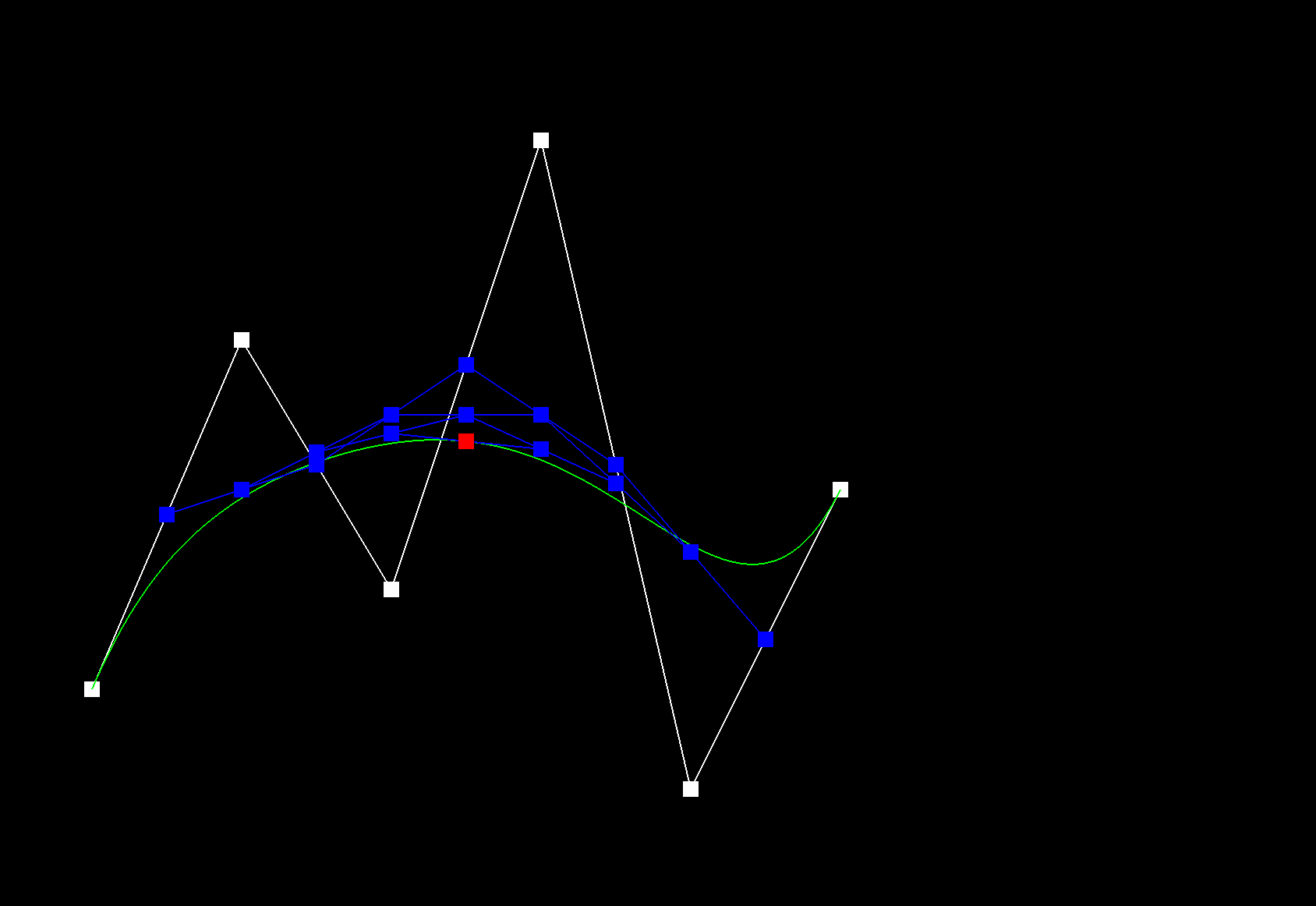
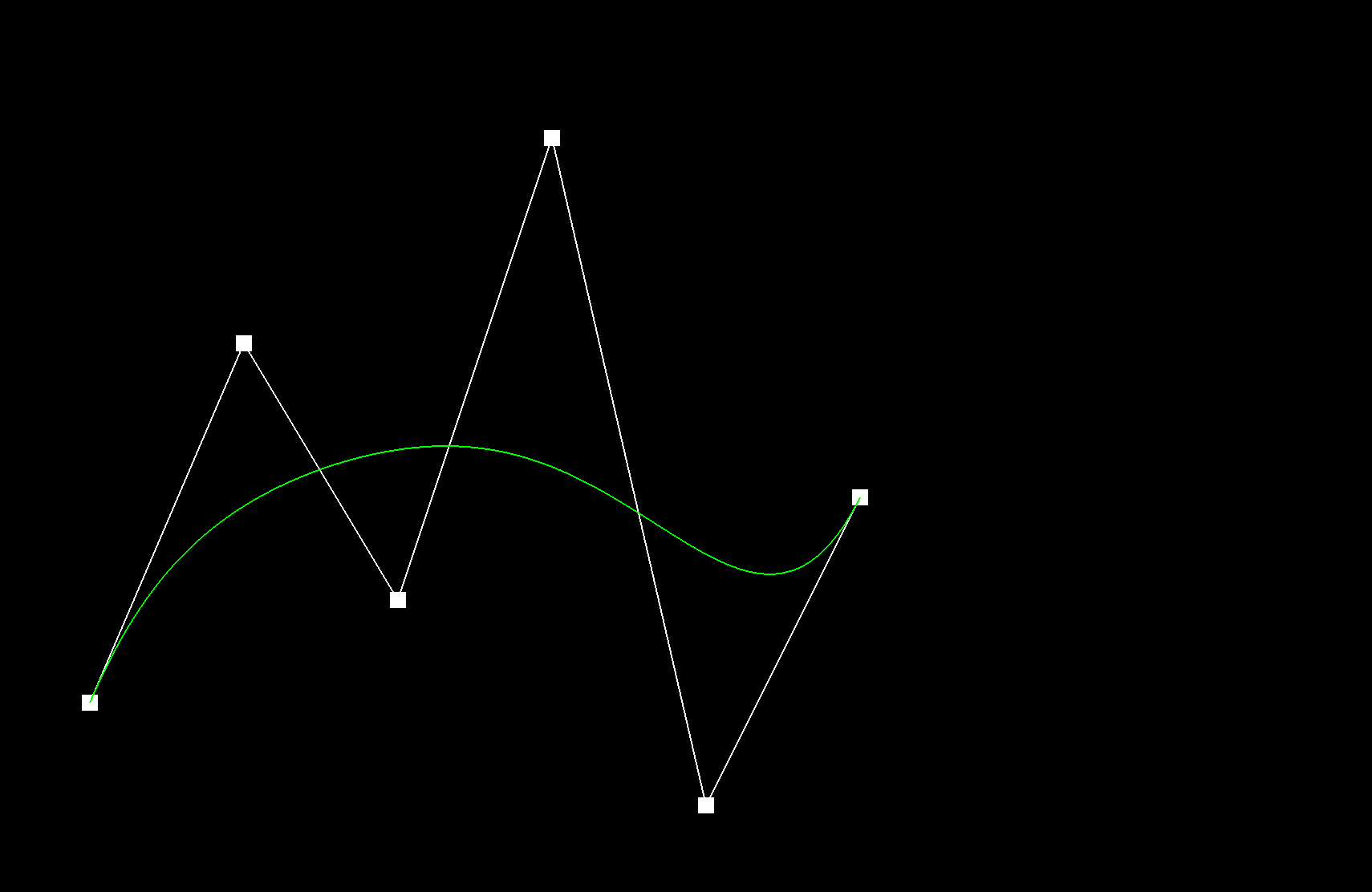
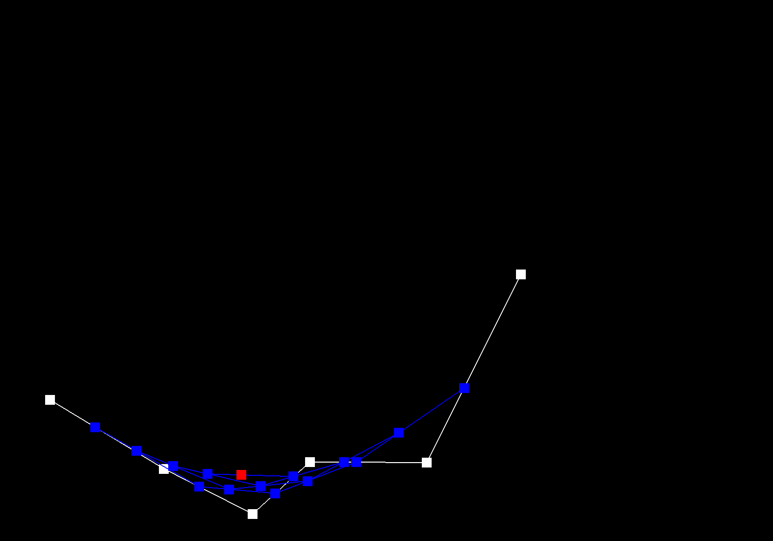
De Casteljau's algorithm recursively linearly interpolates between successful control points of a given curve, for a given parameter t, until only one point remains, which is the evaluated point on the Bezier curve at t. The function evaluateStep performs a single step of De Casteljau's algorithm. A vector of 2D control points is passed in as input. New intermediate points are calculated using linear interpolation: \( p_i^{'} = (1 - t) p_i + t * p_{i+1} \). These intermediate points are stored in a new vector and then returned. This function is repeated called until only one point remains, which is the point on the Bezier curve at t.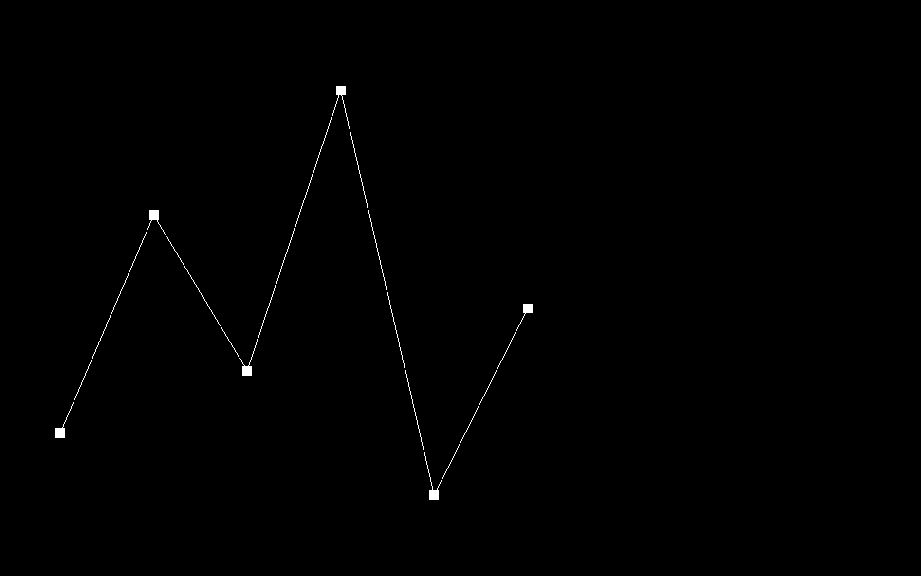 |
 |
 |
 |
 |
 |
 |
 |
 |
Part 2: Bezier surfaces with separable 1D de Casteljau
De Casteljau's algorithm can be extended from Bezier Curves to Bezier surfaces by applying the algorithm twice. First, use de Casteljau on one axis (the u direction), to reduce each row of control points into a single set of intermediate points. Then, use 1D de Casteljau to evaluate the other axis (the v direction) on the resulting intermediate points to obtain the final interpolated point.
evaluate1D, recursively applied de Casteljau's algorithm to a 1D list of control points, using evaluateStep.
The function evaluate, first evaluates each row of control points along the u-direction using evaluate1D. This
reduces a row into a single point. This collapses the 2D input into a 1D list of intermediate points. Then, this 1D list is used
to compute the final interpolated point along the v-direction using evaluate1D.
Section II: Triangle Meshes and Half-Edge Data Structure
Part 3: Area-weighted vertex normals
All ajacent faces of the vertex were iterated through. For each face, the 3 vertices were extracted. The normal of the face was calculated, by taking the cross product of the 2 vectors (using the 3 vertices). This normal was then added to the accumulated sum. Throughout these calculations, the boundary faces were ignored. Finally, the accumulated normal was normalized into a unit vector.
|
|
Part 4: Edge flip
First, I check for boundary conditions: if the edge, or any of the associated edges are boundary ones, return the edge without
flipping. I then got all 6 halfedges, 4 vertices, and 2 faces associated with the two triangles and edge needed to be flipped.
For each halfedge, I reassigned its next, twin, vertex, edge, and face pointer, even if some were unchanged.
This was done using Halfedge::setNeighbors(...) .
Then, for each vertex, edge, and face, I reassigned its new halfedge pointer, even if some were unchanged.
To figure out which pointers or variables I should be assigning to which, I drew it out. I drew out the new configuration of each halfedge and figured out what its new next, twin, vertex, edge and face pointer was. Without my step-by-step diagram, I would not have known where to start!

|
|
|
Part 5: Edge split
In my implementation of the edge split operation, I inserted a new vertex at the midpoint of the split edge. This creates four triangles from the original two and keeping track of all the pointers and variables. I started by keeping track of al the possible elements and allocated memory for 1 vertex, 3 edges, 2 faces, and 6 half-edges.
To aid in debugging, I drew out detailed diagrams of the mesh both
before and after each edge split. This visual approach helped me notice
missing edges and faces as well as segmentation faults that were
occurring due to incorrect connectivity. The diagrams allowed me to
compartmentalize the problem, isolating each component of the operation
until I pinpointed and fixed the errors. Here is the diagram I used to
reference in my code:
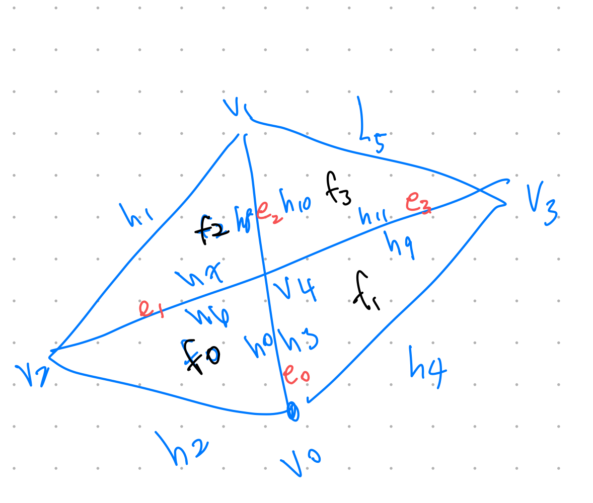
After a couple trial and errors, I was able to successfully implement the half edge split.
|
|
|
|
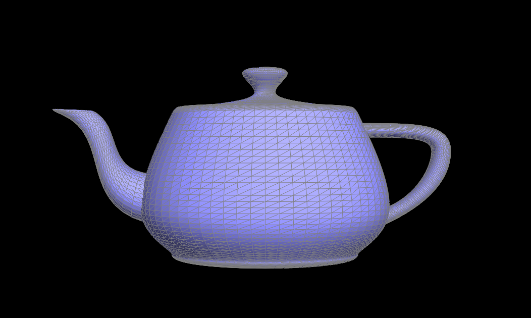
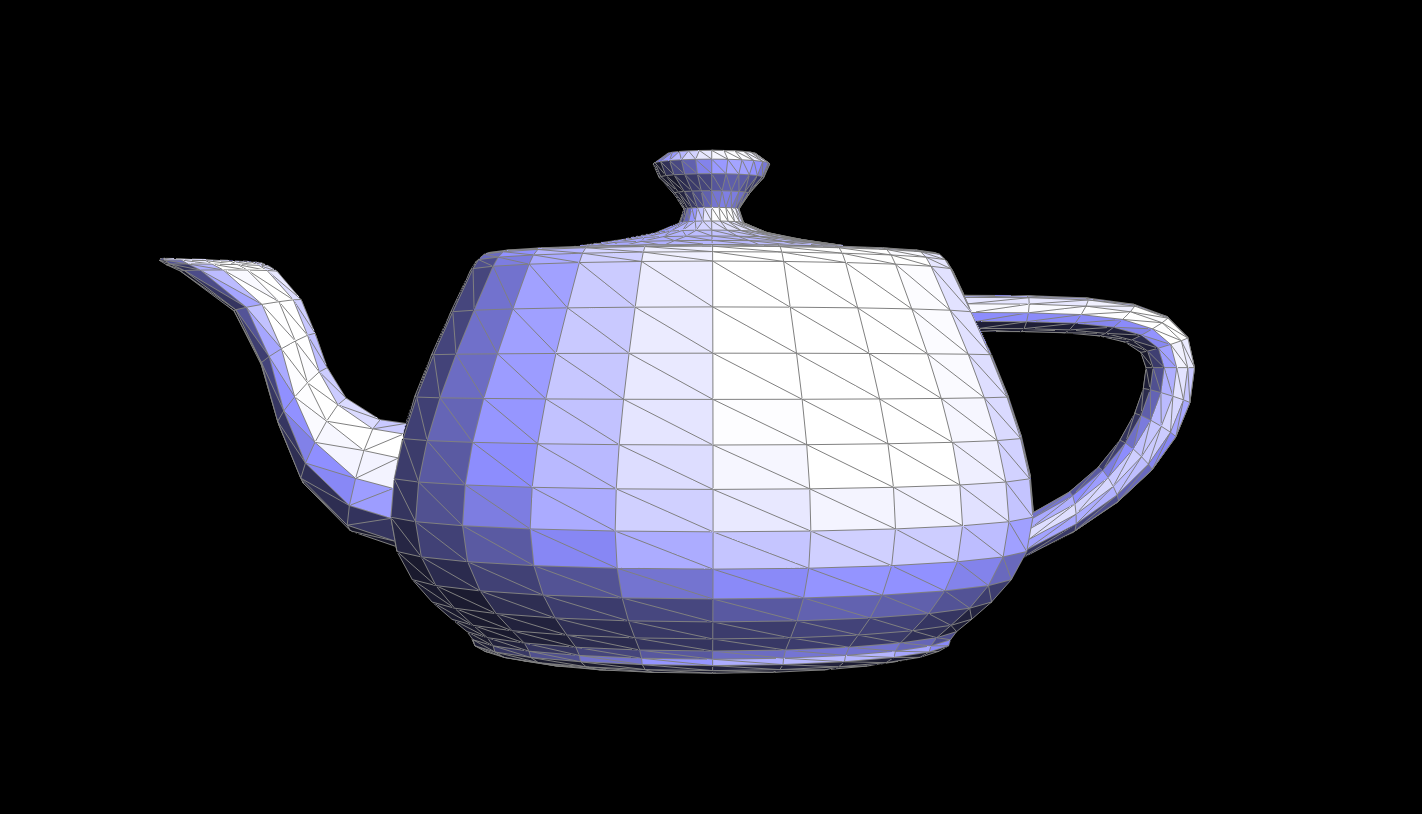
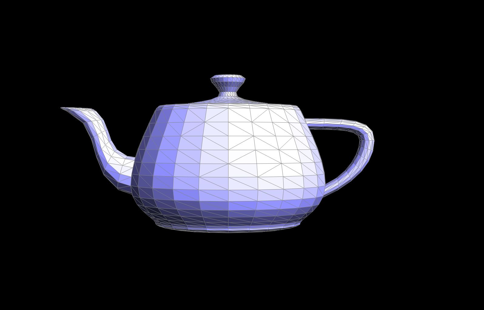
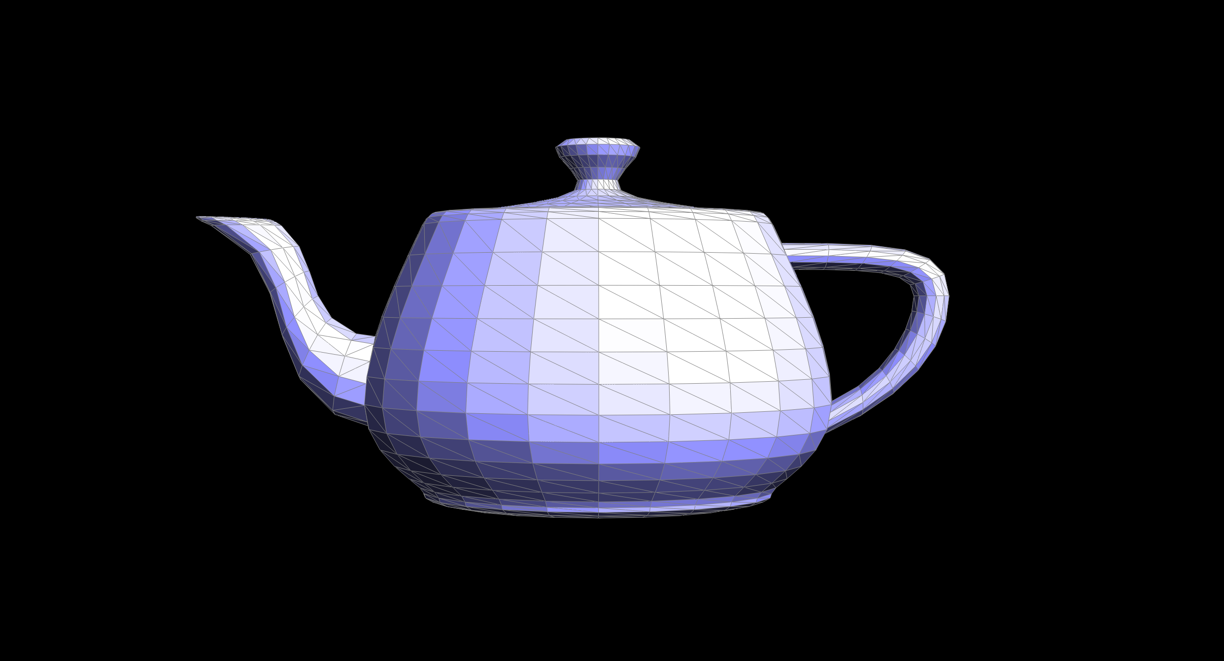
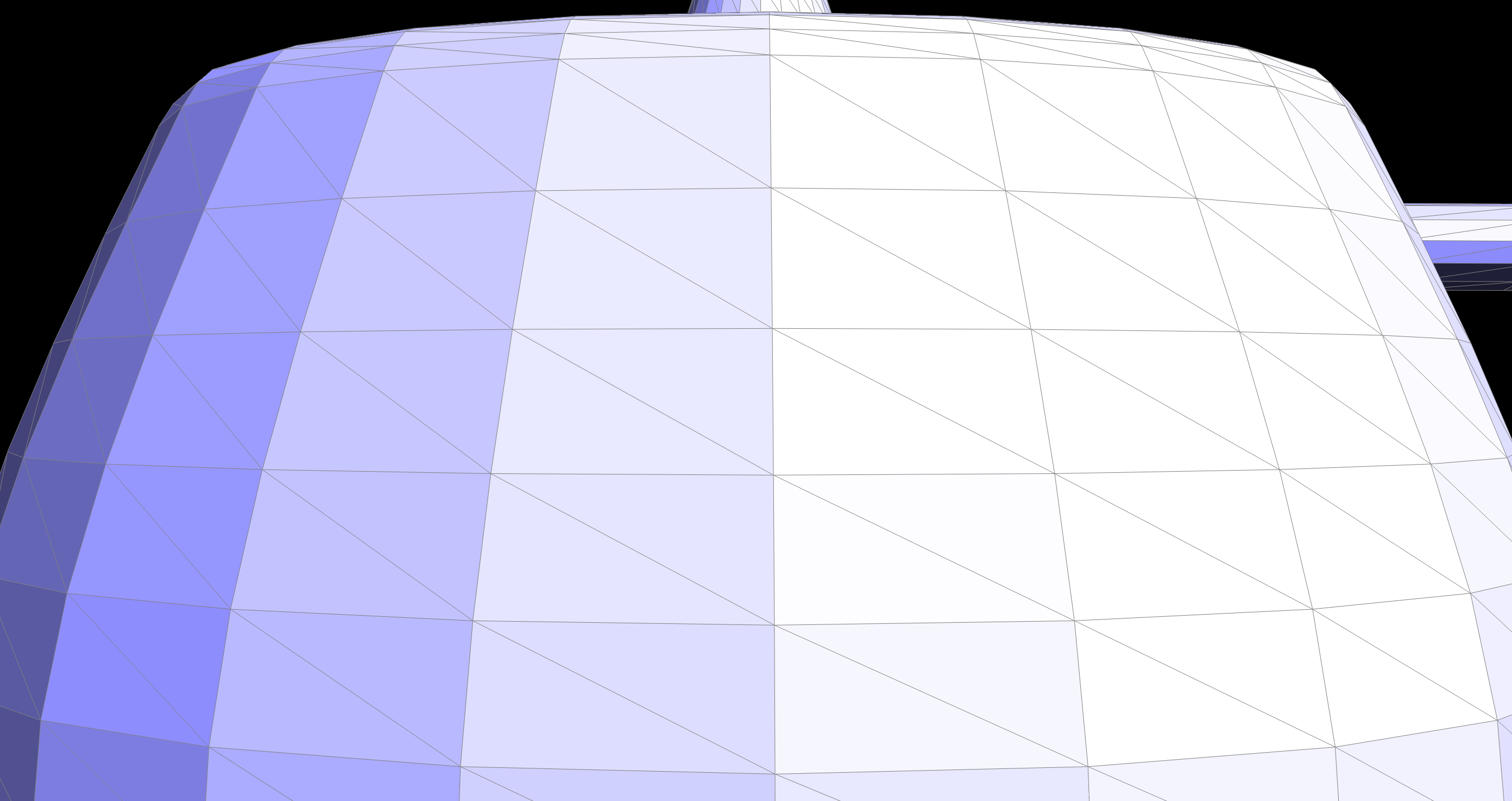
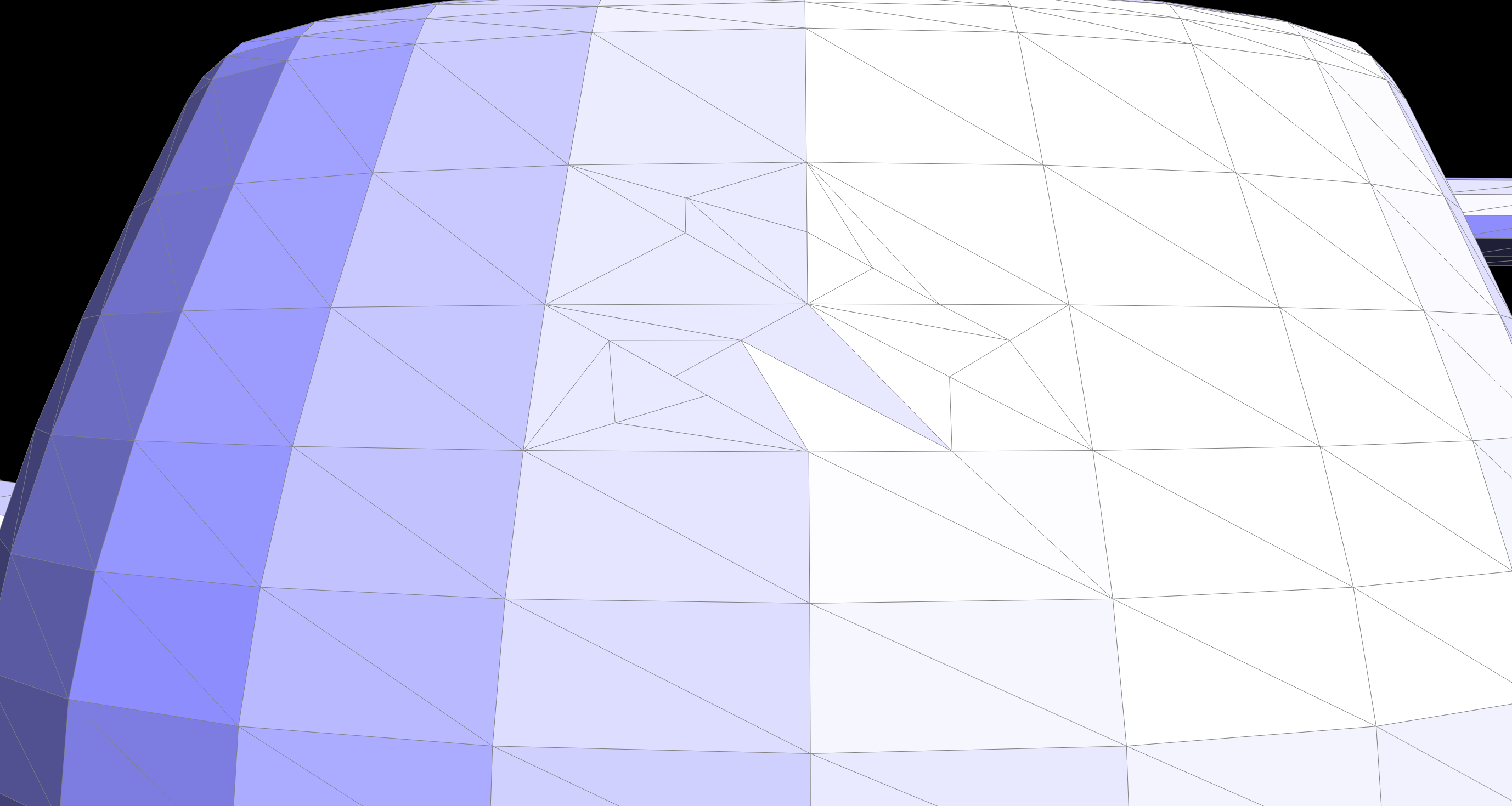
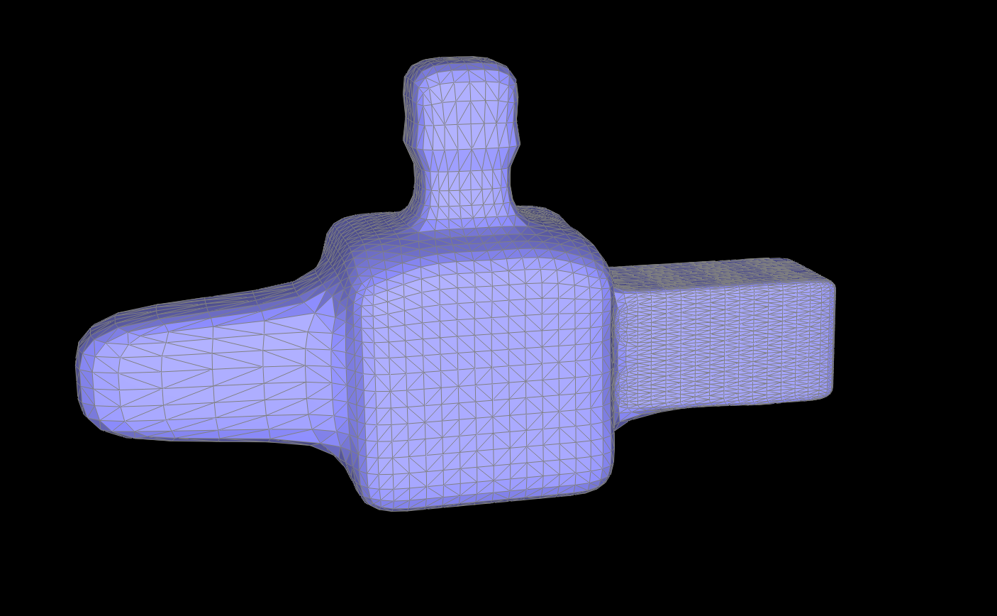
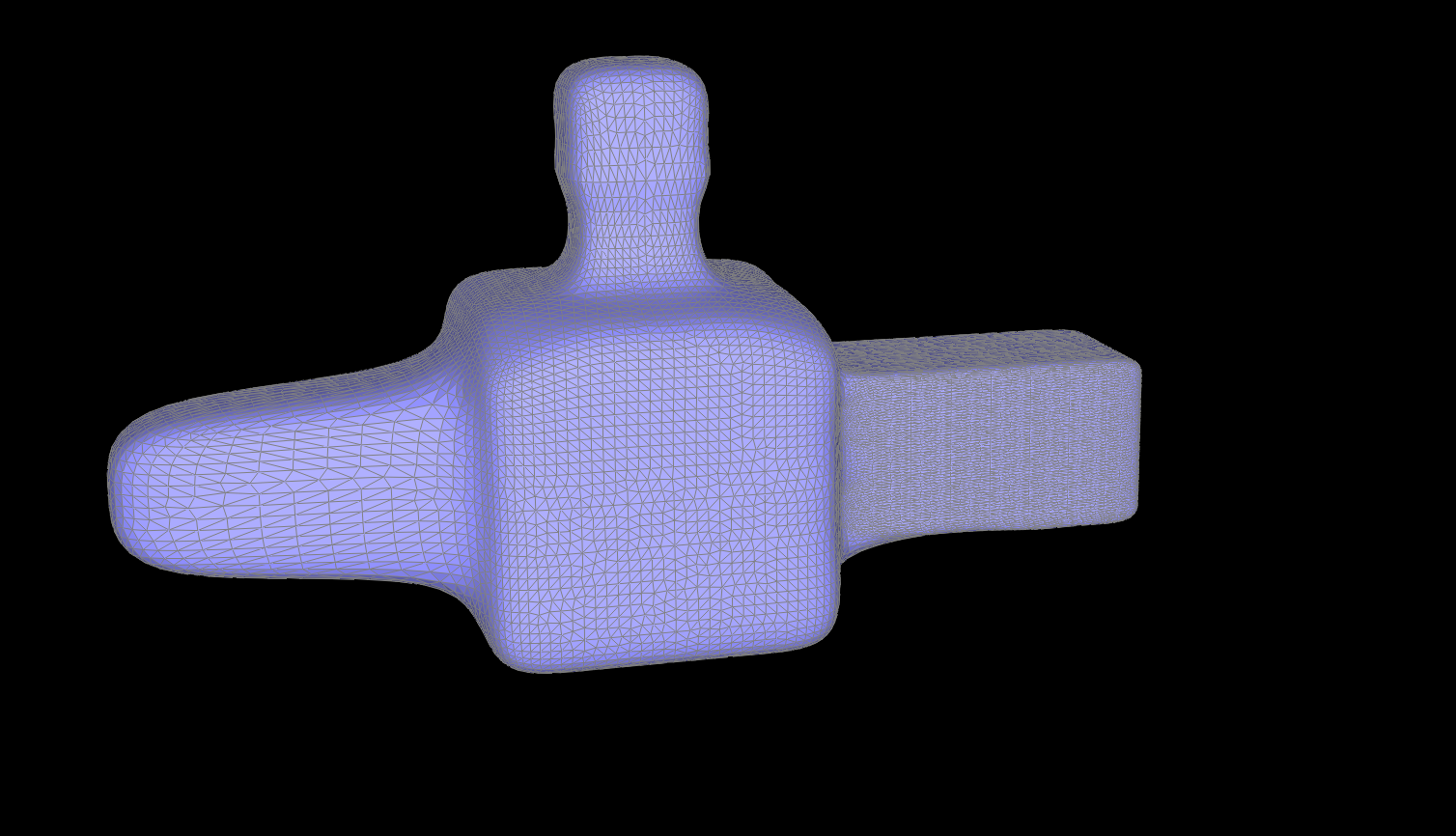
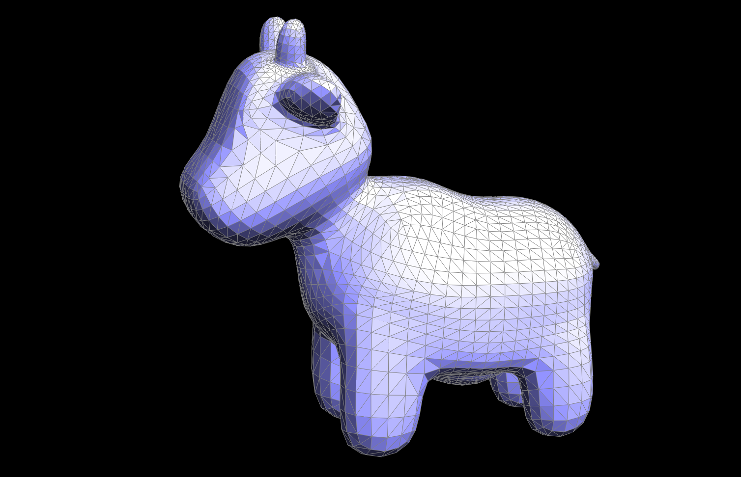
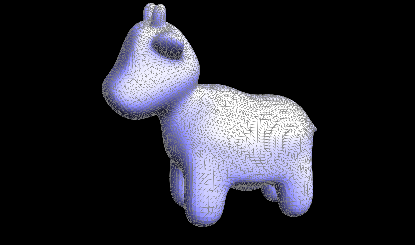
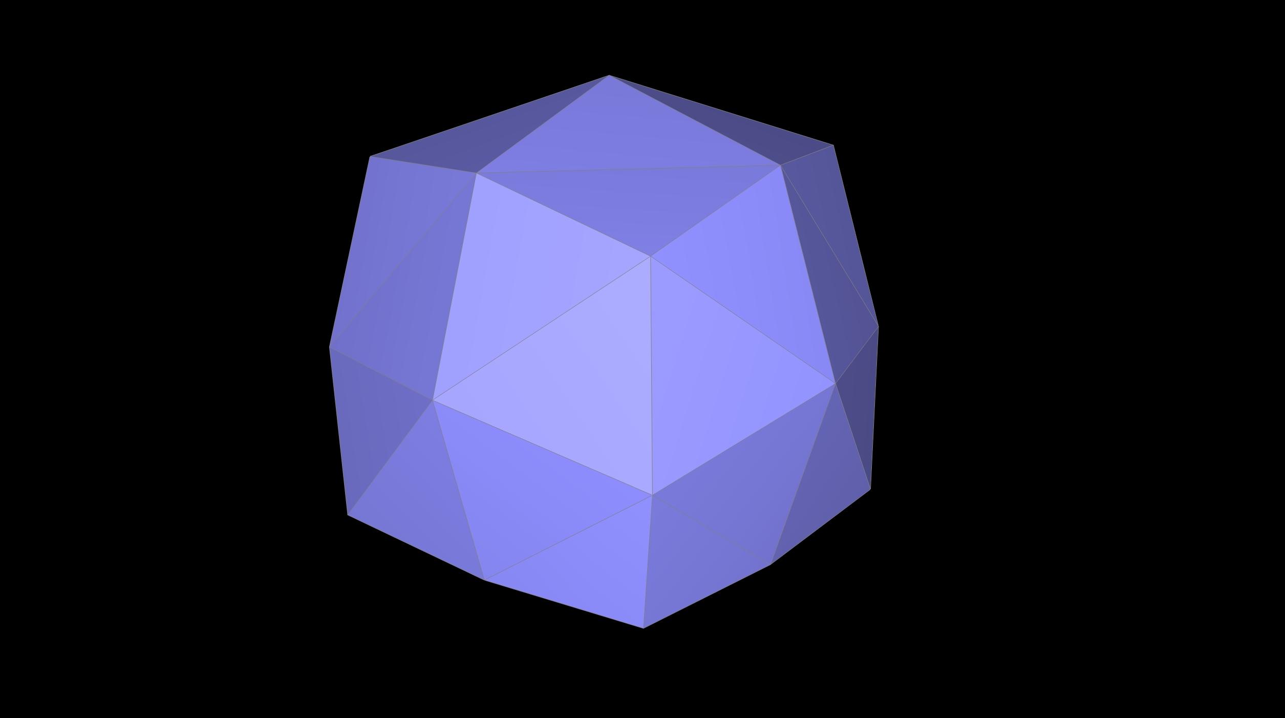
Part 6: Loop subdivision for mesh upsampling
We followed the outline for loop subdivision by computing the new vertex positions for all the original verticies and then used the weighting formula to refine a triangular mesh and create a smoother surface. Since each of the new vertices would be inserted at the We followed the outline for loop subdivision by computing the new vertex positions for all the original verticies and then used the weighting formula. Since each of the new vertices would be inserted at the midpoint of existing edges and store calculate its associated weighting. We then call splitEdge on every edge in the mesh, then we want to flip any edge that connects an old and new vertex.
One of the key parts of this implementation is setting a isNew flag on the new vertecies we create in order to ensure we flip the correct edges. This is the area I faced alot of difficulty with, especially in debugging, as in my original output it would look almost correct—the meshes were upsampled, but the wrong edges were flipped and it was hard for me to figure out why. I ended up needing to look into a smaller example (ex. the cube) where it was easier for me to visually see wahtt he problem was and where my edges were being flipped incorrectly.
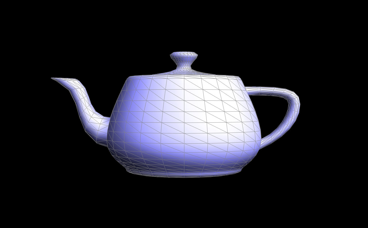
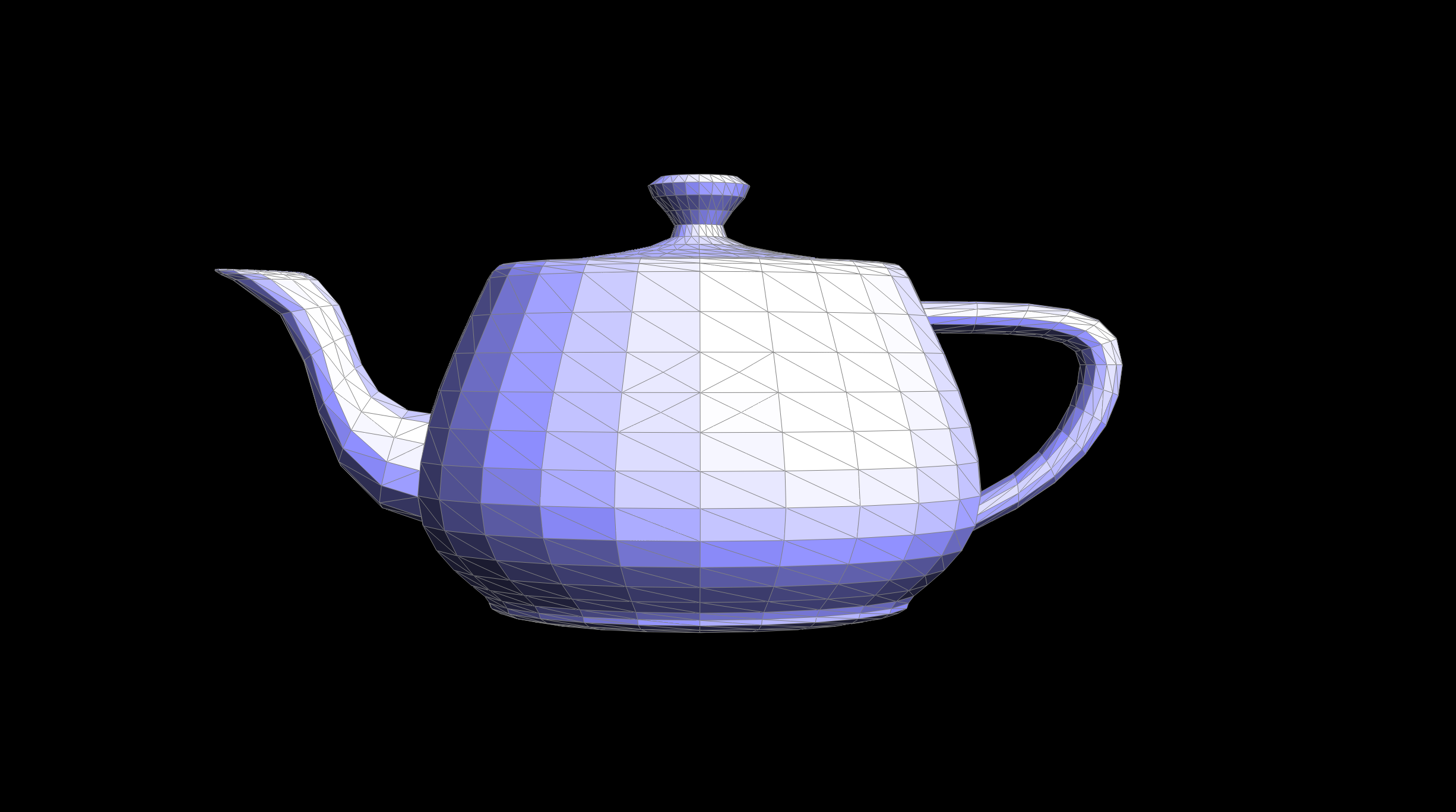
The results were as follows:
|
|
|
|
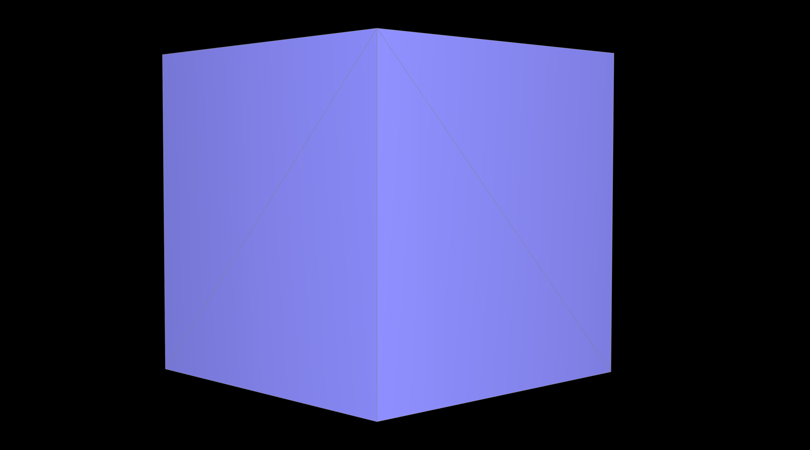
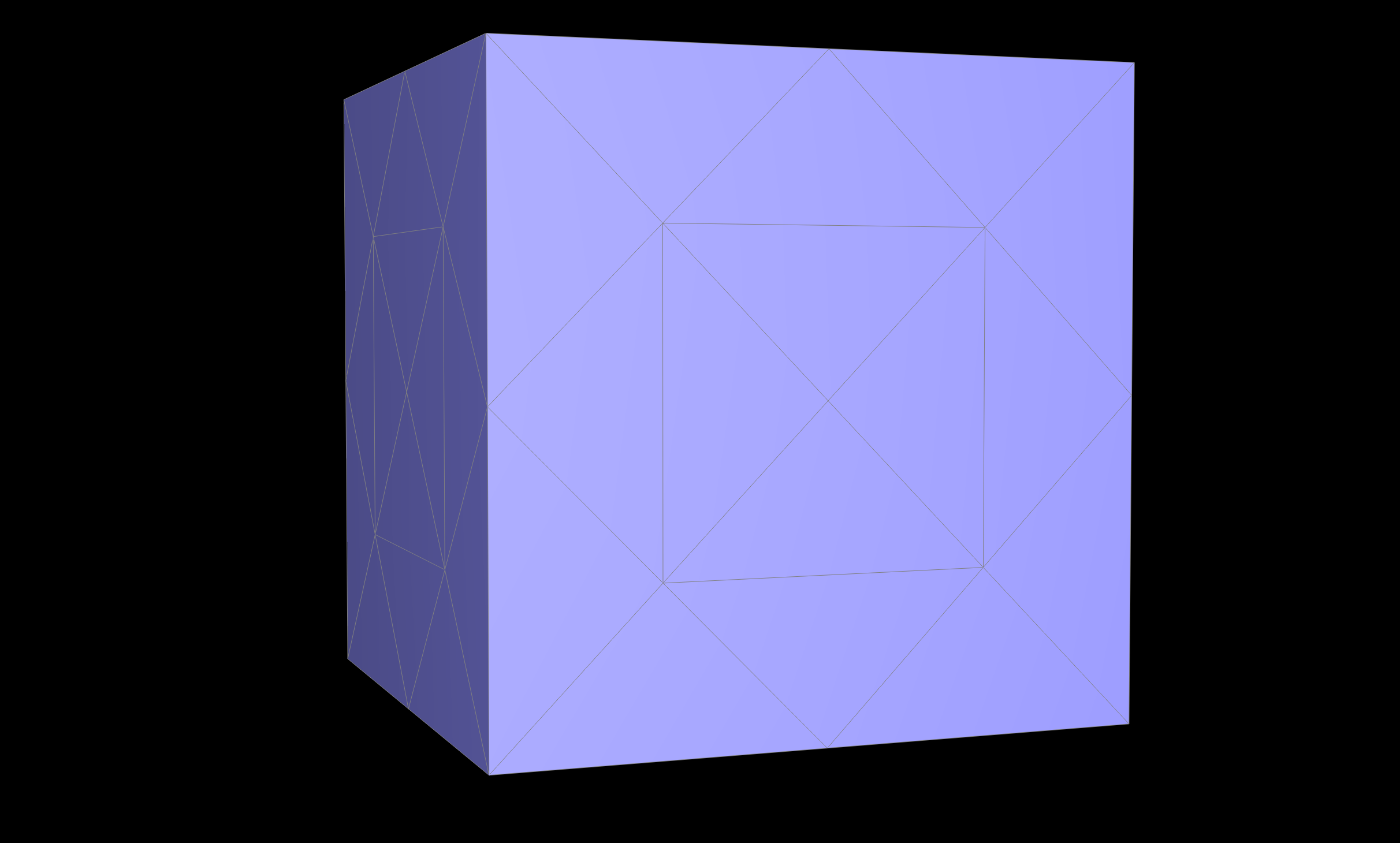
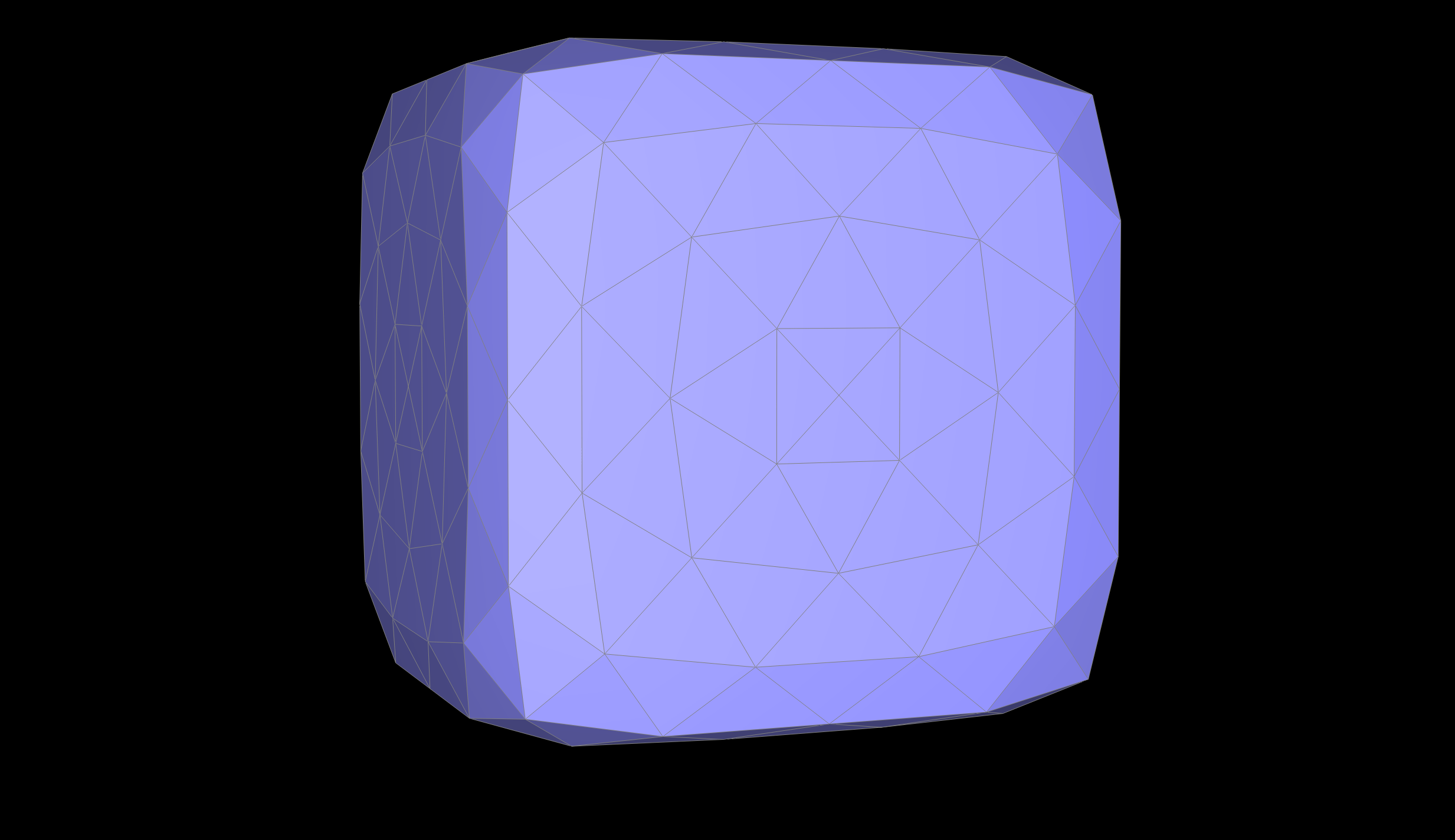
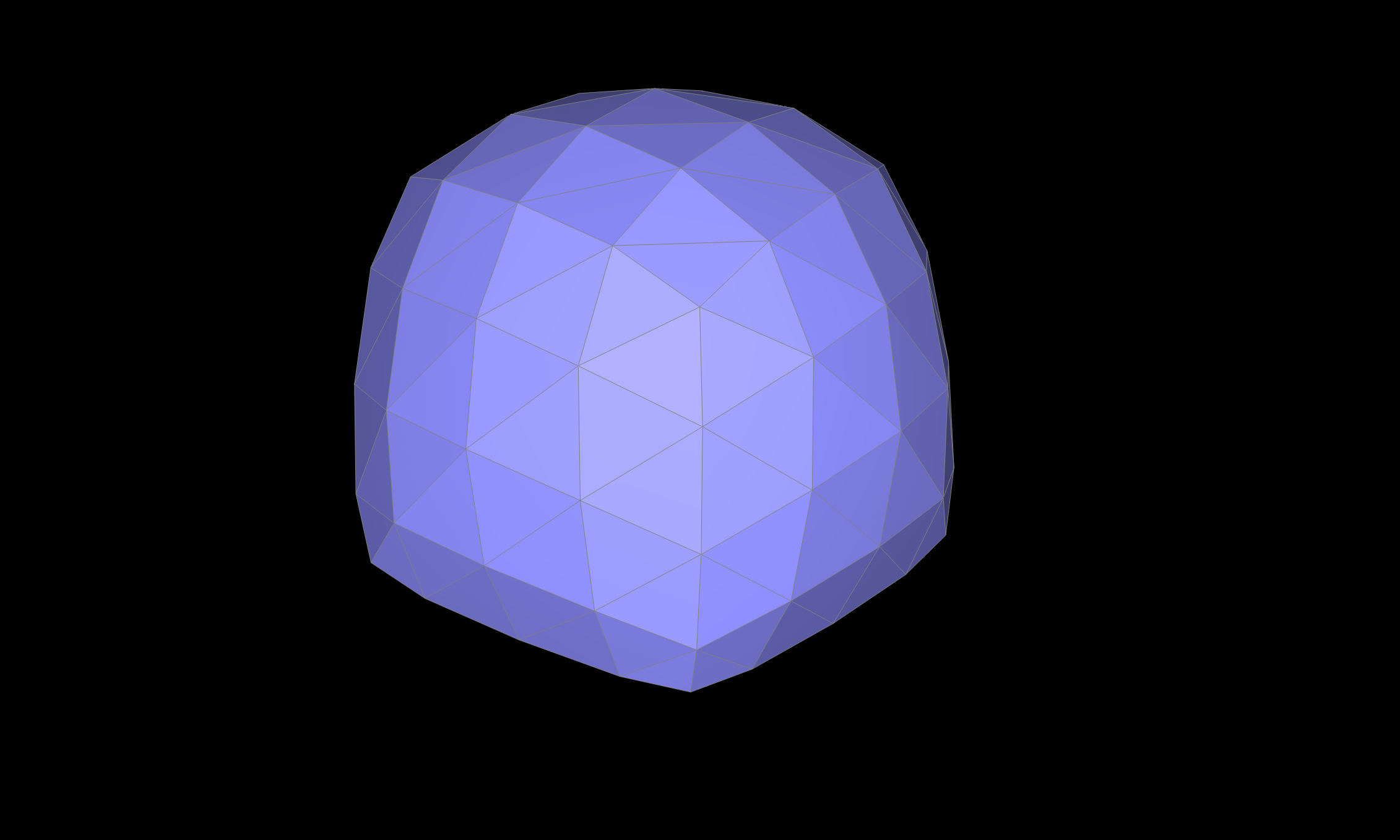
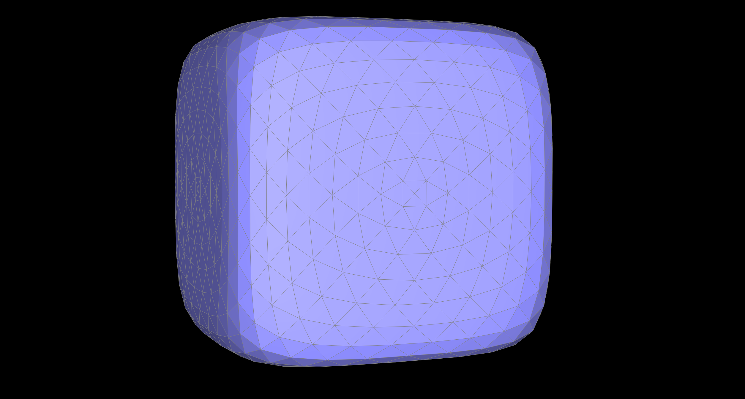
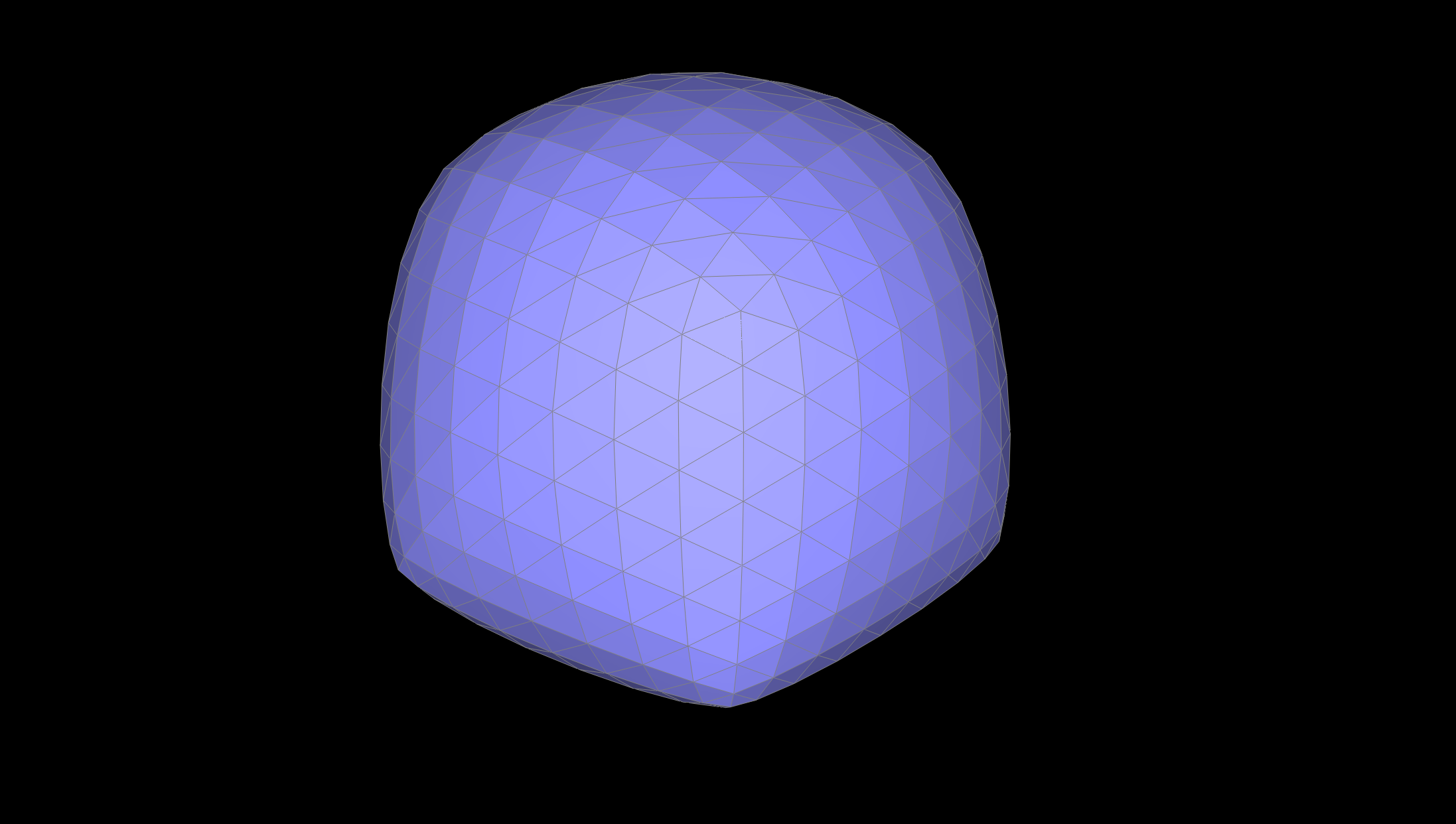
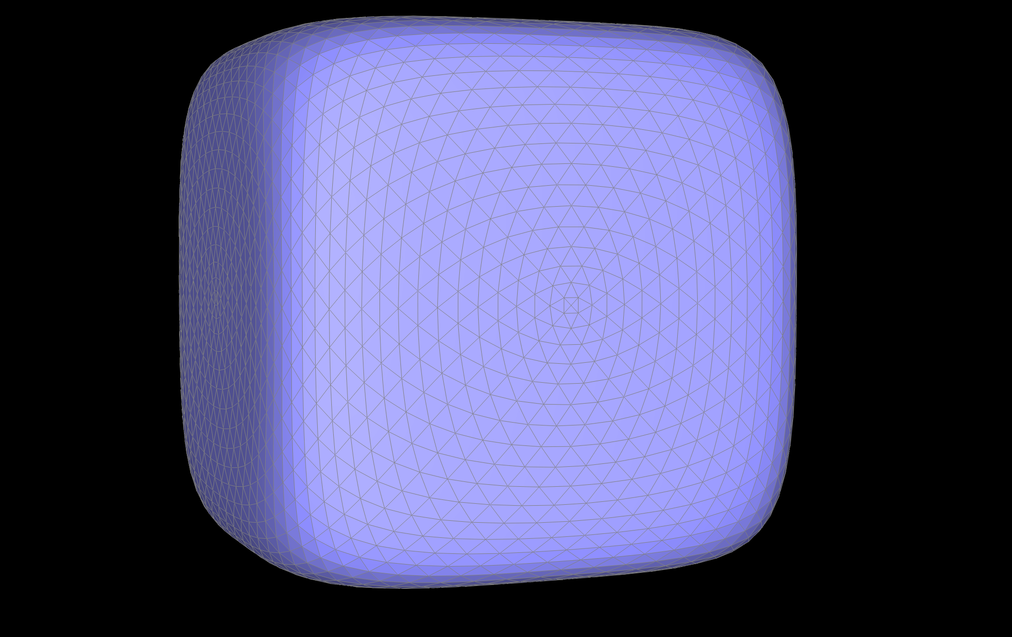
Sharp corners where edges meet appear more pointy after subdividion than corners where there are less edges meeting, which would be more flat. We can see this in the below cube example where in the original upsampling of asymmetric mesh, some edges have more edges meeting in certain corners than others, so greater edge corners are more defined in the final subdivision resulting in an inaccurate upsampled result.
I also played around with edge flips and splits to better subdivide some of the meshes. I realized that by evenly subdividing the cube, I could create better upsampled meshes. This is so that most of the vertices have the same degree and have symmetrical edge splits alleviating the effects of upsampling sharp corners
|
|
|
|
|
|
|
|